But we have so much electronic around us, it is a must to understand the basics of these devices, how it work and how their logic in the process are. These are the very basic logic of the computing processes. These are called 'Logic Gates'.
AND Gate
Truth Table[1]:
Chip Diagram:
NAND Gate
Boolean Expression:
(A ⋅ B)' = Q
Logic Diagram:
Truth Table[1]:
Chip Diagram:
OR Gate
Boolean Expression:
A + B = Q
Logic Diagram:
Truth Table[1]:
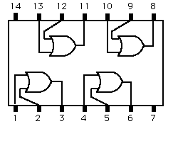
Chip Diagram:
Cite
Pictures:
- Picture taken by me
- AND, OR, NAND, NOR, XOR Gate symbol draw by myself using google draw.
[1] - IB SL Computer Science textbook chapter 4
- AND Gate chip diagram <http://www.gestialba.com/public/electronica/anagramas/eletacast004.jpg>
- NAND Gate chip diagram <http://www.dzsc.com/icstock/uploadfile/200942512456885.jpg>
- OR Gate chip diagram <http://hyperphysics.phy-astr.gsu.edu/hbase/electronic/ietron/or3.gif>
- NOR Gate chip diagram <http://upload.wikimedia.org/wikipedia/commons/2/2a/NOR_Pinout.jpg>
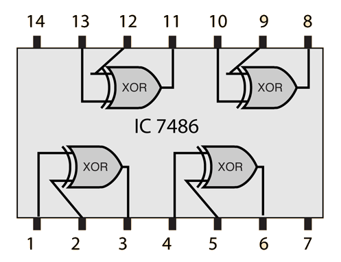
- XOR Gate chip diagram <http://hyperphysics.phy-astr.gsu.edu/hbase/electronic/ietron/xor6.gif>
Sources:
- IB Standard Level Computer Science Textbook Chapter 4
Material used:
- 74SL08, AND Gate chip.
- 74SL00, NAND Gate chip.
- 74SLXX, OR Gate chip.
- 74SLXX, NOR Gate chip.
- 74SLXX, XOR Gate chip.
DISCLAIMER: This article are used for educational purpose only.


